Difference between revisions of "Assembly"
Jump to navigation
Jump to search
| Line 10: | Line 10: | ||
[https://player.vimeo.com/video/568114940 Time lapse of assembly] | [https://player.vimeo.com/video/568114940 Time lapse of assembly] | ||
'''Current version is designed for absolute simplicity so as little as possible SMD components and parts with large footprints are used. Start assembling by soldering the | '''Current version is designed for absolute simplicity so as little as possible SMD components and parts with large footprints are used. Start assembling by soldering the smallest parts first (MMBT3904 + MCP3426). | ||
<br>Then add THT passive parts piece by piece according to description on the PCB and the BOM.''' | <br>Then add THT passive parts piece by piece according to description on the PCB and the BOM.''' | ||
Revision as of 22:21, 7 July 2021
Requirements:
- Screwdriver
- Solder Iron
- Solder
- Flux
- 3D Printer / 3d printing service
- bcMeter Parts
Watch Time Lapse!
Current version is designed for absolute simplicity so as little as possible SMD components and parts with large footprints are used. Start assembling by soldering the smallest parts first (MMBT3904 + MCP3426).
Then add THT passive parts piece by piece according to description on the PCB and the BOM.
Most important:
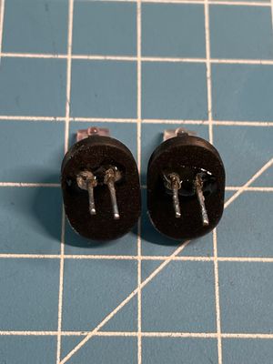
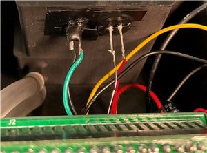
- Place IRL81A (IR Emitter) and LPT80A (Sensor) in adapters D and E, seal with hot glue and solder wires to the corresponding vias on the PCB. Long leg is anode (positive).
- Place adapters D and E in the case A and B. Emitter to top case. Seal with (hot) glue or tape.
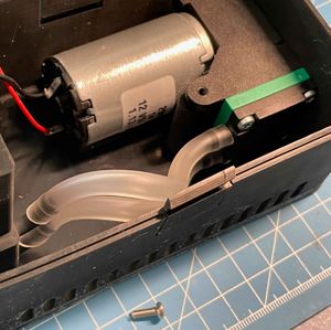
- Put pump in place and do a test run for leakage.


