Assembly
Overview of parts / Assembly
Requirements:
- Screwdriver
- Solder Iron
- Solder
- Flux
- 3D Printer / 3d printing service
LED and sensor brackets
The orientation of both the 3D printed infrared LED and sensor assemblies have been simplified to reduce orientation mismatches. The infrared LEDs come in a clear looking part while the infrared sensors are dark parts. Each part needs to be correctly oriented; they have an spherical shaped part (lenses) which needs to point to the shorter end of the 3D printed brackets in a way that they both point to the filter paper.
Insert LED and sensor bracket assembly to the case
Prepare both the counterparts for the LED and sensor bracket assemblies with superglue or hot glue before insertion to create airtight channels. Make sure to also completely cover the middle part between sample and sensor area with glue. This is absolutely crucial to avoid air leakage. Before inserting the brackets into the case, use superglue to fix the LEDs and sensors in place (avoid tilting and
check orientation). Mount the brackets to the case and check that the lenses of are centered in the holes by looking straight from above; same goes for the dark infrared sensors in their bracket to be inserted in the bottom case. You have a little while to adjust with superglue; using hot glue, reheat the area as needed: Clean possible residue of glue with acetone as it affects the clarity of the LEDs. Reference & Sample parts
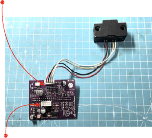
In this area on the circuit board, the LEDs have to be connected in series, so the negative pin of the first LED is the positive pin of the second LED. Using a standard 4 pin 2.54mm JST connector and cable, solder the connections in the order red- black-yellow-white.
Here, the infrared sensors for measuring the attenuation are connected parallel. Thus, they have to be connected in a different order than the LEDS: black-red-white-yellow. Now, you have completed the most crucial part of the bcMeter assembly. The orientation of the LEDs to the sensors and the air leakage have a huge influence on the later accuracy of the device. Smaller isalignments can't be avoided and compensated by the "Calibration" function from the interface. Sealing
Now we can continue assembling the case itself by adding the rubber seal onto the bottom part. Make sure that the diameter is very well known as this is a crucial parameter for accuracy. Check for air leakage and if needed, add a second seal on the top part as well. Make sure that the holes a overlapping. To verify the diameter, you can just let the paper run black and then check the form and size of the sample spot. Also add the M3 screw threads to the poles and use superglue to make a solid connection.
Pump control circuit
The bcMeter is very forgiving in choosing pumps since I tested and used every available type.
Basically you can connect every pump you want which is able to run at 5V. There are two type pumps in the low cost range: Membrane and propeller. For our use case, we need the membrane pumps. Then, they can have a PWM controller (Type A) or run without (Type B). The bcMeter is able to handle both types of pump and you can just connect them to the PCB. For PWM pumps, remove Q4.
image
image
If you want to use an airflow meter, connect the input of the pump to the output of the airflow sensor as shown on the left.
The input of the airflow sensor needs to be connected to the air sampling connector.
The pump output needs to be connected to the air output of the bcMeter as shown on the right.
Finalizing the built Screw the top part of the case handtight
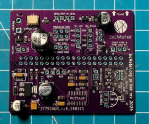
Technical overview of the PCB:
U1: MCP3428 4 Channel Analogue / Digital Converter D1 / D2: IR LED connector for sensor and reference
Q1 / Q2: IR Phototransistor for sensor and reference (ADC Channel 1 and 2) J1: Omron D6F Airflow Sensor (ADC Channel 4)
J2: SSD1306 Display (optional J7: Heater or Fan (optional) J12: SPI Header (optional)
J5: Air Pump
J4: PWM + J9 Power for Air Pump (Remove Q4 for PWM Pump!)
+ several header (I2C, ADC, Power) for expandability


