Assembly
Basic Requirements: Solder Iron / Solder / Flux / 3D Printer
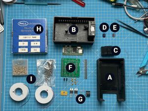
3d Print – STL Files are attached A: Upper Case B: Lower Case C: Intake manifold D: LED/Sensor holder
Order (links for convenience, parts are off-the-shelf / available in any regular workshop) F: PCB from pcbway.com, jlcpcb.com or anywhere else (~$20) – find gerber files for upload attached G: Components from mouser.com or anywhere else (~$40) – shopping cart to import on mouser attached. H: Order filter papers (~$50) – Pack of 50 sufficient for at least 1000 samples. Type TBD, tested with T60A20 – ask local labs for availability I: Additional material: Hot Glue ~$7 Rubber band (SHORE A) for sealing ~$11 M3 Screws ~$3 M3 threads ~$7 microSD Card (4gb+) 40 Pin Header (optional for plug the Hat) J: Order membrane pump (~$160) - here (TBD – cheaper solution may be available soon)
STL for 3D Printing (SLA or FDM) attached. Print on any 3d printer or send to any service provider. Use black filament / resin. If possible, use flex filament or mix resin with flex resin. 200g Resin / FDM ~ $5-$10
Assembly Instructions Current version is designed for absolute simplicity so as little as possible SMD components and parts with large footprints are used. Start assembling by soldering the smalles parts first (MMBT3904 + MCP3426). Then add THT passive parts piece by piece according to description on the PCB and the BOM.
Place IRL81A (IR Emitter) and LPT80A (Sensor) in adapters D and E, seal with hot glue and solder wires to the corresponding vias on the PCB. Long leg is anode (positive).
Place adapters D and E in the case A and B. Emitter to top case. Seal with (hot) glue or tape.
Put pump in place and do a test run for leakage. Apply hot glue if necessary
