Device assembly
Template:BcMeter Assembly Documentation
bcMeter 2025 Assembly Documentation
LED and Sensor Brackets
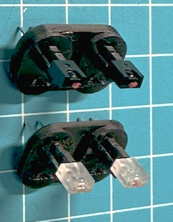
The orientation of both the 3D printed infrared LED and sensor assemblies has been simplified to reduce orientation mismatches.
The infrared LEDs are housed in clear-looking parts while the infrared sensors are in dark parts. Each must be correctly oriented – note that the spherical lens on each part should point toward the shorter end of the bracket, ensuring both point toward the filter paper.
- Glueing: Use plastics glue (avoid "super glue" as it can leave residue that affects LED and phototransistor sensitivity for days or weeks). Place a droplet of glue on each leg to close the hole.
- Assembly:
 * Insert the LED and sensor bracket assembly into the case.
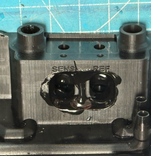
 * Pre-treat both counterparts with plastics glue before insertion to create airtight channels.
 * Ensure the middle section between the sample and sensor areas is completely covered with glue to prevent air leakage.
- Fixing: Prior to insertion, secure the LEDs and sensors with plastic or hot glue (avoid tilting; check orientation).
- Mounting: Once inserted, mount the brackets to the case and verify that the LED and sensor lenses are centered.
Reference & Sample Parts
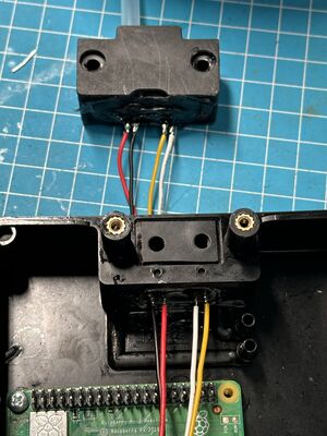
On the circuit board, the LEDs must be connected in series. The negative pin of the first LED serves as the positive pin for the second LED. Use a standard 4-pin 2.54 mm JST connector and cable, soldering the connections in the order
:red – black – yellow – white - connect one by one. If your order of cables has another coloring, adhere to that.
The infrared sensors (used for measuring attenuation) are connected 'in parallel. Their connections must follow a different order from the LEDs, given the same color order:
:black – red – white – yellow
This completes the most crucial part of the bcMeter assembly, as the LED-to-sensor orientation and air leakage directly affect the device’s later accuracy. Minor misalignments are unavoidable but can be compensated by the "Calibration" function in the interface.
Sealing
Continue the case assembly by adding a rubber seal to the bottom part. Key points include:
- Ensure the seal’s diameter is precisely known—it is critical for accuracy.
- Check for air leakage; if needed, apply a second seal to the top part and ensure the holes overlap.
- To verify the diameter, let the paper run black and examine the sample spot’s form and size.
- Add M3 screw threads to the poles and use superglue to secure the connection.
Pump Control Circuit
The bcMeter is versatile with pump selection. Any pump that can run at 5V will work. There are two low-cost pump types:
- Membrane pumps – Recommended for this use case.
- Propeller pumps
Membrane pumps can either use a PWM controller (Type A) or operate without one (Type B). The bcMeter can handle both; simply connect the pump to the PCB. For PWM-controlled pumps, remember to remove Q4.
Airflow Meter Setup
If an airflow meter is used, configure the connections as follows:
- Connect the pump’s input to the airflow sensor’s output.
- Connect the airflow sensor’s input to the air sampling connector.
- Connect the pump’s output to the bcMeter’s air output (note that the exact connection may vary with case revision).
Finalizing the Build
- Insert the filter paper and screw the top part of the case by hand.
- Connect a stronger 12V pump and cover the air inlet.
- If any noise is heard (indicating leakage), use glue to seal the gap.
Description of the Components
- U1: MCP3428 4-Channel Analogue/Digital Converter
- D1 / D2: IR LED connector for sensor and reference
- Q1 / Q2: IR Phototransistor for sensor and reference (ADC Channels 1 and 2)
- J1: Omron D6F Airflow Sensor (ADC Channel 4)
- J2: SSD1306 Display (optional)
- J7: Heater or Fan (optional)
- J12: SPI Header (optional)
- J5: Air Pump
- J4 / J9: PWM + Power for Air Pump (remove Q4 for PWM pump)
- Additional: Several headers (I2C, ADC, Power) for expandability
Case Assembly Overview
For the final assembly, refer to the detailed instructions above covering:
- Pump control circuit
- Final build adjustments
- Component descriptions


